China's Steel Corrugated Pipe Culverts: The Smart Choice for Global Infrastructure
Corrugated Steel Pipe Design for Flood Control: A Case Study in Hydraulic Engineering
Meta Description: Discover how corrugated steel pipes were selected for a large-scale flood drainage project. This case study covers material comparison, hydraulic design, settlement control, and waterproofing strategies for corrugated metal culverts
2. Material Selection
The engineering design incorporated hydrological and topographical conditions to calculate flow capacity, determining a design diameter of 3.5m for the flood drainage pipeline. Three pipe materials met the requirements: reinforced concrete pipe (RCP), prestressed concrete pipe (PCP), and corrugated steel pipe (CSP).
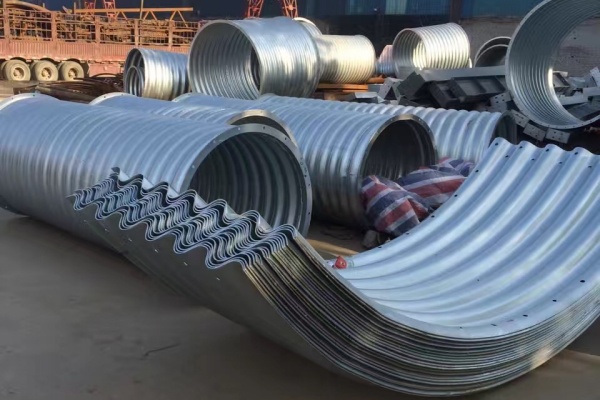
Reinforced concrete pipe and prestressed concrete pipe offer advantages including high pressure resistance, low roughness coefficient, and mature connection technology. However, their significant weight requires crane installation. Given that the project area sits on artificially compacted fill foundation, the pipe trench would require concrete foundations with large dimensions, resulting in substantial construction volume and high project costs. Corrugated steel pipe demonstrates high strength and excellent pressure resistance, with lower costs for diameters above 3.5m compared to concrete alternatives. Comparative analysis showed that using corrugated steel pipe saves approximately 40% in comprehensive unit cost per linear meter compared to reinforced concrete pipe, delivering significant economic benefits. Corrugated steel pipe also exhibits strong adaptability to complex terrain, lightweight characteristics for convenient transportation, on-site assembly capability, and simple rapid construction. Therefore, corrugated steel pipe was selected.
3. Pipeline Design
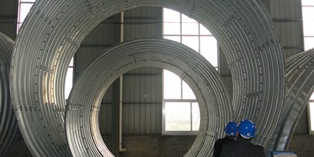
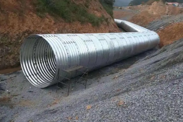
Through preliminary consultation and market research, two types of corrugated steel pipe meeting the design cover thickness requirements were identified: monolithic pipes for diameters up to 3.0m, and assembled pipes for diameters exceeding 3m. Three diameters—3.0m, 3.5m, and 4.0m—were evaluated to determine the most economical option satisfying flow capacity requirements. The main pipeline extends 2.17km with a bottom slope gradient of 0.04 to 0.06. Currently, no design specifications for corrugated steel pipe exist in the water conservancy industry, so the design referenced provincial highway engineering standards, adopting a roughness coefficient of 0.033. Based on project layout, a regulating reservoir was installed on the main pipeline with tributary pipes joining along the route. Flow capacity calculations employed culvert hydraulic formulas, determining flow regimes within each pipe section based on flow rate, diameter, upstream water level, pipe length, and slope gradient, with iterative calculations using appropriate formulas
3.2 Internal Force Calculation
According to the "Highway Corrugated Steel Culvert Technical Specifications" (TCECSG:D66-01-2019), internal forces in corrugated steel pipe should consider wall pressure from permanent loads, variable loads, and seismic effects. For this project, the pipe has only overburden soil of 11m thickness with no vehicle traffic or live loads, eliminating variable loads. The project area has seismic intensity VI, so seismic effects were excluded. Design pressure at the pipe crown considers only permanent loads, specifically pressure from the upper fill material.
3.3 Foundation Settlement Design
The longest single pipeline in this project reaches 2.16km, with the pipeline foundation located in artificially leveled and compacted channels. Although corrugated steel pipe exhibits strong deformation adaptability, uneven compaction during construction of artificially compacted channels could cause differential settlement and subsequent pipe deformation. Accordingly, the pipe trench received specific treatment. First, the pipeline foundation was processed by compacting the excavated trench, laying a 0.7m thick 3:7 lime-soil cushion with layered compaction achieving at least 95% density, topped with 0.3m coarse sand cushion having grain size no larger than 12mm, and backfilling with excavated material. Expansion joints were installed at connections between corrugated steel pipe and large concrete structures such as regulating reservoirs and stilling basins, at locations with inconsistent foundation strata lithology, and at boundaries between excavation and backfill sections. However, due to limited use of expansion joints in similar projects and insufficient research on their effectiveness for corrugated steel pipe, further study on the settlement prevention performance of different expansion joints is needed.
3.4 Waterproofing Design
Waterproofing for assembled corrugated steel pipe primarily depends on panel installation methods and sealing materials. Based on previous experience with corrugated steel pipe, the waterproofing structure for assembled pipe adopts a lap joint configuration, where two corrugated plates overlap and are connected by bolts passing through both plates. In this process, gaps between plates, through-holes penetrating the plates, and clearances between bolts and holes all represent potential leakage points. The primary leakage location in this connection method is at circumferential lap joints. Leakage occurs mainly because flexible foundations experience uneven settlement within months after backfill completion, causing some lap joints to undergo tension while others experience compression. Bolts no longer remain in their original positions, leading to sealing material displacement and creating leakage points. The main leakage points are at circumferential lap joints, with leakage primarily caused by uneven settlement in flexible foundations during the months following backfill completion, resulting in tension at some lap joints and compression at others, bolts shifting from original positions, sealing material displacement, and consequent leakage points.

 Products