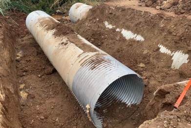
Corrugated Metal Pipe Culvert Design & Load Calculation – Easy Guide for Engineers
Corrugated PipeCulvert Design & Load Calculation – Easy Guide for Engineers
1. Overview
We put together a fill‑height vs. structure comparison table based on both local and international data. The calculation method we used has been tested and works really well. When designing a corrugated metal pipe culvert, the main steps are: calculate the load acting on the pipe, figure out the allowable stress, and then pick the right pipe specs – things like wave length, wave height, wall thickness, and diameter.
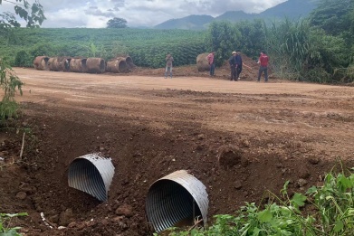
Before you start designing, you need to do a site survey and decide where to place the culvert. Besides soil properties and drainage, you also have to think about construction cost and long‑term maintenance (keep it low). Here’s what to consider in the design phase:
(1) Based on hydrology, hydraulics and other service needs, decide the structure type, size, shape, alignment and slope.
(1) Based on hydrology, hydraulics and other service needs, decide the structure type, size, shape, alignment and slope.
(2) The structure must be strong enough to handle the pressure from the embankment and live loads, and also resist water flow erosion.
(3) Choose materials that won’t wear out or corrode easily.
(4) Factor in initial material & installation cost, maintenance cost, and annual extra expenses.
2. Analysis & Design
The first thing in design is to figure out the loads on the culvert. Basically two types: - Dead load (DL) – from the fill above and any stationary weight on the road. - Live load (LL) – from moving vehicles.
Dead load increases as the fill height goes up; live load becomes less important. For buried corrugated pipes, you have both soil pressure and traffic load. In highway use, when fill height is over 5 m (16 ft), you can ignore live load. For railways, the cutoff is 9 m (30 ft). Then only dead load matters.
2.1 Determining the opening size and foundation depth
Opening size is worked out from head loss, flow velocity, and discharge – plus some clearance – using hydraulic calculations.
Foundation depth depends on pipe diameter and soil conditions. Usually we use gravel‑sand mix, with a thickness of 0.5–0.55 × pipe diameter, minimum 0.6 m (2 ft), maximum 1.5 m (5 ft). The sand/gravel should have less than 5% clay/silt content, max grain size 50 mm (2 in), and compaction degree 85–90%.
To prevent frost heave, use coarse soil with <5% fines for backfill beside the pipe, and compact it to the same level as the roadbed at that depth.
2.2 Relationship between compaction degree and load coefficient K
(from Handbook of Steel Drainage & Highway Construction Products) shows the relationship. We typically choose 80% compaction, which gives a load coefficient K = 0.85. - If fill height ≥ pipe diameter: PV = K × (DL + LL) - If fill height < pipe diameter: all load goes straight to the pipe → PV = DL + LL
2.3 Relationship between internal compressive stress and design stress
Because the load on the culvert is axially symmetric, we only analyze the top half. The relation between surface load PV and internal compressive stress C is: C = PV × R where R = culvert radius. For total pressure Pb (MPa) that the pipe can take, we look at its resistance to deformation. At 80% compaction, Pb is divided into three stages: (1) Pb = 228 when D/R < 294 (2) Pb = 276 – 0.00056 × (D/R)² when 294 < D/R < 500 (3) Pb = 34×10⁶ / (D/R)² when D/R > 500 Where D = span of the corrugated pipe, R = wave radius. - Stage 1: steel just starts to yield – minimum yield pressure. In design we often take this as total pressure. - Stage 2: both yielding and bending happen together. - Stage 3: mainly bending deformation. Safety factor = 2, so design pressure Pc = Pb / 2.
2.4 Determining the wall thickness
From the internal compressive stress C and design pressure Pc, we get the required cross‑section area A: A = C / Pc (unit: mm² per mm width – i.e., area per 1 mm width along the pipe’s length) Then pick a thickness from the manufacturer’s table that meets or exceeds this A value. The table typically lists wave pitch × wave height, thickness, and cross‑section area A (mm²/mm), plus wave radius R.
3. Design Example
Given: - Pipe diameter = 1.5 m (5 ft) - Fill height above pipe = 55 m (180 ft) - Wave pattern = 200 mm × 55 mm (pitch × height) - Soil unit weight = 19 kN/m³ (≈ 120 pcf) Step 1 – Dead load DL = 19 × 55 = 1045 kN/m² (≈ 150 psi) Step 2 – Live load LL = 0 (because fill height >5 m) Step 3 – Design pressure PV = 1045 kN/m² Step 4 – Hoop (circumferential) stress C = PV × diameter / 2 = 1045 × 1.5 / 2 = 783.75 kN/m (≈ 53.7 kips/ft) Step 5 – Allowable design stress Ultimate stress fb = 230 MPa → design stress fc = 230 / 2 = 115 MPa (≈ 16,700 psi) Step 6 – Required cross‑section area A = C / fc = 783.75 / 115 = 6.81 mm²/mm Step 7 – Look up actual area from table For wall thickness 6.0 mm, area A = 7.10 mm²/mm – which is greater than 6.81.
Conclusion: Use a 1.5 m diameter corrugated pipe with 6.0 mm wall thickness. It meets the requirement.
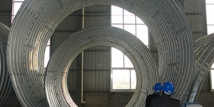

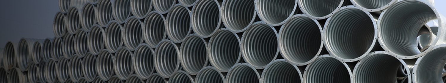
 Products