How long does the entire coating system (galvanizing plus polymer) last in a typical highway tunnel?
Steel Corrugated Plate Tunnel Reinforcement: The Definitive Guide to Construction Specifications and Quality Assurance
Aging tunnel infrastructures worldwide face increasing challenges from material fatigue, seismic shifts, and evolving load demands. Among the most reliable and cost-effective rehabilitation methods is the installation of steel corrugated plates within existing tunnel linings. This technique not only restores structural capacity but also provides a ductile, corrosion-resistant shell that extends service life for decades. However, the long-term success of such reinforcement hinges entirely on rigorous adherence to detailed construction specifications. From initial material certification to final waterproofing tests, every step demands precision, foresight, and a deep understanding of geotechnical and structural interactions. This comprehensive guide consolidates industry best practices, codified standards, and field-proven procedures into a single, actionable resource for civil engineers, site superintendents, and quality assurance teams.
1. Essential Pre-Construction Preparations and Site Setup
Before a single steel plate is lifted into place, meticulous groundwork must establish the conditions for a successful installation. This preparatory phase is often underestimated, yet it accounts for a significant portion of potential failures or costly rework.
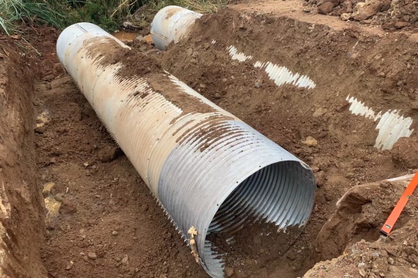
Material Verification and Handling Protocols The integrity of the entire reinforcement system originates in the factory. All steel corrugated plates must undergo stringent factory acceptance testing, adhering strictly to national or international standards for corrugated steel products. Crucially, a trial assembly—or pre-erection fit-up—should be conducted at the manufacturing facility to identify any mismatched hole alignments or fabrication errors before materials are shipped to the often-remote tunnel site. Upon arrival at the project location, every single plate must be visually and dimensionally inspected. Transportation can introduce warping, edge damage, or bolt-hole distortion, and any plate showing signs of deformation must be immediately quarantined and returned. Furthermore, no material is permitted to enter the work zone without a corresponding, valid product quality certificate. This documentation provides traceability for steel grade, galvanizing thickness, and rolling processes, which are vital for verifying compliance with design life requirements, especially in aggressive groundwater environments.
Surface Preparation and Substrate Conditioning
The existing tunnel lining—whether concrete, masonry, or shotcrete—must provide a stable and conforming substrate for the new steel shell. Prior to installation, the tunnel interior must be thoroughly cleaned to remove all loose debris, hydrocarbon deposits, dust, and protruding reinforcement bars. High-pressure washing or sandblasting may be necessary to achieve a surface that allows for intimate contact and effective grout adhesion. Additionally, any standing water or active leaks in the lining should be temporarily diverted or sealed, as moisture can compromise the initial bonding of sealants and the compaction of later backfill grouts. A clean, dry, and level surface is the bedrock of a durable composite structure, preventing stress concentrations that could lead to premature fatigue in the corrugated steel.
Accurate Surveying and Reference Marking
Precision measurement is the compass for the entire installation. Survey teams must accurately re-establish the tunnel’s centerline, cross-sectional profile, and longitudinal gradients. This involves setting clear elevation control points and marking reference lines along the sidewalls, haunches, and crown. These benchmarks dictate every subsequent step, from the positioning of the first plate to the final alignment of the last segment. Survey errors, however small, accumulate during sequential installation, leading to misaligned connections, uneven grout gaps, and potentially catastrophic geometric deviations at the tunnel portal connections. Therefore, using total stations or 3D laser scanning for initial and periodic checks is highly recommended to ensure that every plate sits precisely within the design envelope.
2. Systematic Installation Techniques and Connection Strategies
With preparation complete, the installation phase commences. This stage requires a careful balance between construction speed and uncompromised precision, as the structural behavior of the corrugated shell depends on correct assembly sequencing and tight connections.
Determining the Optimal Assembly Sequence
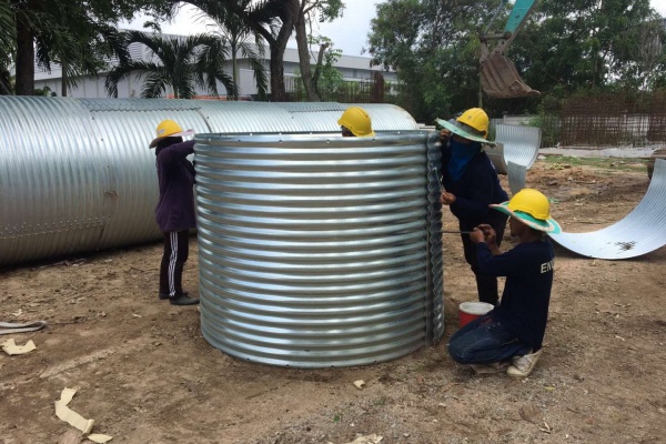
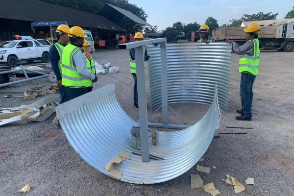
The chronological order of plate placement significantly influences installation safety and final fit. Generally, work progresses from one end of the tunnel section toward the other. However, the vertical sequence is determined by site logistics and existing clearance. When adopting a bottom-up sequence, installers begin by placing and temporarily supporting the sidewall plates, then proceed to the arch haunch sections, and finally position the crown plate at the apex. This method is preferred when heavy lifting equipment is limited, as it allows smaller cranes or hoists to handle lower segments first. Conversely, in a top-down approach, the crown plates are installed first, followed by the haunch, and lastly the sidewalls. This strategy is often employed when overhead access is available and when early closure of the top section is required for immediate rockfall protection above the working area. Regardless of the chosen path, the installation must always follow a strictly documented method statement approved by the structural engineer.
High-Strength Bolted Connections and Torque Control
Adjacent corrugated plates are unified using high-strength friction-grip bolts, which must match the specified grade, diameter, and thread pitch. The integrity of this bolted seam is paramount; it must transfer shear forces across joints and prevent relative movement under cyclic traffic loads. During assembly, the bolt holes must be precisely aligned. Forcing misaligned plates with drift pins can elongate holes and compromise the bolted connection's fatigue resistance. Once properly aligned, bolts are inserted and tightened using calibrated torque wrenches to achieve the exact tension or torque value stipulated in the design calculations. To safeguard these critical connection points against future corrosion, the bolt recesses are typically sealed with a high-performance structural adhesive, followed by an overall spray application of anti-corrosion primer and a topcoat. This dual-protection approach not only prevents thread seizure—which would complicate future inspections—but also creates a watertight barrier over the most vulnerable entry points.
Anchoring Mechanisms and Lateral Stability
To ensure the newly installed steel shell remains firmly pressed against the existing lining and does not shift under ground pressure, robust anchoring systems are indispensable at the base and along the sidewalls. For T-type structural frames, once a corrugated plate is accurately positioned against the existing concrete, it is fixed in place using nail-shaped expansion anchors or fully grouted rock bolts. These anchors are fitted with specialized nuts or clamping plates that tighten against the steel surface, providing immediate restraint. For H-type frames, which often incorporate a lower cutout to accommodate foundation works, the plates are inserted through this opening and mechanically hoisted to the crown. After reaching the design elevation and making contact with the old lining, these plates are secured with chemical resin anchors. Chemical anchors offer superior performance in cracked or low-strength concrete substrates, as the resin penetrates into micro-fractures to create a bond often stronger than the concrete itself.
Maintaining Geometric Accuracy and Tolerances
Aesthetically and structurally, the finished surface must present a smooth, continuous arch free from sharp deviations. The longitudinal invert must maintain a steady, consistent gradient—any reverse slope or “birdbath” formation can lead to water pooling, accelerating corrosion and freeze-thaw damage within the gap. The interior of the assembled structure must be completely clear of construction spoils, dropped tools, or stone fragments that might become lodged between the old and new linings. Moreover, the alignment of the corrugated pipe opening must seamlessly integrate with the approach embankment or portal structures. End elevations, particularly at the ring joints, must be checked against the original survey markers with a maximum permissible deviation of just a few millimeters, as these interfaces are critical for attaching transition sections and waterproofing membranes.
Implementing Staggered Longitudinal Joints
One of the most nuanced yet critical aspects of corrugated plate assembly is the arrangement of longitudinal seams. Rather than aligning all vertical seams continuously along the tunnel length, industry standards mandate a **staggered joint pattern**. This means that the vertical seam of one ring is offset from the seam of the adjacent ring—often by a distance equivalent to one to two corrugation pitches. Why is this so important? Under seismic activity or differential ground settlement, the tunnel experiences complex stress distributions, including vertical compression, horizontal thrust, and torsional shear. A staggered arrangement prevents continuous “weak paths” along a single line of bolts, thereby distributing these forces evenly across a larger steel area. This redundancy significantly enhances the system’s ductility and its ability to accommodate ground movements without catastrophic joint failure.
3. Comprehensive Waterproofing and Leakage Control Systems
Water ingress is the primary adversary of steel infrastructure. The interface between the new corrugated steel and the old concrete lining is inherently a void that must be meticulously sealed to protect against chemical attack, rust formation, and hydraulic uplift.
Rubber Waterstop Integration at Perimeters
At the peripheral edges where the corrugated steel terminates against the existing tunnel arch, durable rubber waterstops are installed. These elastomeric profiles are placed circumferentially around the entire cross-section. Their purpose is to act as a flexible, impervious gasket that accommodates minor thermal movements and differential settlement between the steel and the old concrete. The waterstops must be vulcanized or spliced with airtight seals at joints to ensure continuity. Without this peripheral seal, groundwater under hydrostatic pressure would quickly find its way through the narrow annular gap, leading to persistent seepage that undermines the structure’s durability.
Strategic Grout Injection and Gap Filling
The annular void between the corrugated plate and the host lining is not a passive space; it must be actively filled to create a unified, composite structural section and to stop water pathways. Cementitious grouts—often modified with micro-expansive agents—are the materials of choice for this application. Micro-expansive grouts are specifically preferred over standard Portland cements because they counterbalance the natural shrinkage that occurs during hydration and drying. To prevent trapped air voids and ensure uniform distribution, the injection process is strictly controlled. Contractors employ a zonal injection strategy, dividing the tunnel arch into distinct sections (sidewalls, haunches, crown). The process proceeds in stages, with a predetermined injection height, a measured waiting period to allow initial setting, and a specific pressure limit to avoid displacing the steel plates. Ventilation holes, drainage pipes, and monitoring outlets are strategically placed along the arc. The technician knows the void is completely filled when grout begins to flow consistently from the uppermost monitoring port, providing visual confirmation that the entire gap has been saturated.
Sealing Injection and Ventilation Ports
Once the primary grouting is complete, the temporary ports used for injection and venting become potential leak points. These apertures are meticulously cleaned and backfilled with a high-grade, non-shrink cement mortar to restore the steel plate's continuous surface. To provide an extra layer of security against water wicking through these mortar plugs, a separate back-mounted waterstop strip—often a butyl rubber tape—is applied directly over the exterior of each filled hole. This redundant sealing ensures that even if micro-cracks form in the patch, moisture cannot bypass the waterproofing envelope.
4. Robust Anti-Corrosion Coatings for Extended Service Life
Steel's greatest weakness in underground environments is its susceptibility to electrochemical corrosion, driven by moisture, oxygen, and dissolved salts. Consequently, the protective coating system is not merely an aesthetic finish—it is a functional component of the structure.
Hot-Dip Galvanizing as the Primary Barrier
The foundational protection for the corrugated plates is provided by hot-dip galvanizing. In this process, the steel is immersed in molten zinc, creating a metallurgically bonded alloy layer. The thickness of this coating is specified by mass per unit area, often demanding a benchmark such as 1200 grams per square meter (or approximately 85 microns thickness). This substantial coating provides cathodic protection: even if the surface is scratched down to the steel, the surrounding zinc corrodes preferentially, sacrificially protecting the exposed steel edge. The quality of galvanizing must be inspected for uniformity, adherence, and freedom from blisters or bare spots, as any deficiency at this base layer compromises all subsequent treatments.
Polymer Overcoating for Enhanced Chemical Resistance
For tunnels subjected to particularly aggressive conditions—such as those carrying industrial runoff, located near coastal saltwater, or exposed to de-icing chemicals—a secondary polymer overcoat is applied over the galvanized layer. This plasticized coating (often PVC, polyethylene, or polyurethane) serves a dual function: it acts as a physical shield against abrasive particles in drainage water, and it provides a dielectric barrier that interrupts the electrical circuit necessary for electrolytic corrosion. The combination of a thick zinc layer and a robust polymer skin creates a composite defense that can effectively extend the maintenance-free service interval of the reinforcement to over 100 years in moderate environments.
5. Rigorous Quality Inspection and Assurance Protocols
Quality control is not a final step but a continuous thread woven through every phase of construction. Systematic testing and observation are vital to validate the work done and to document compliance for handover.
Visual and Dimensional Conformity
A comprehensive visual sweep of the completed installation is the first line of defense. Inspectors check that the plates are straight and free from buckling, that joint flanges are flush, and that there is no evidence of unintended gaps. The surface should be pristine—free from the red rust of failure, mechanical gouging, or deformation caused by dropping heavy tools. Simultaneously, dimensional checks are performed using calibrated tapes and laser measures. The effective internal diameter, the overall length of the reinforced section, and the wall thickness of the steel are verified against the approved shop drawings, ensuring deviations remain strictly within the allowable tolerances specified by the design code.
Bolt Tension Verification
Because the bolted seams are the structural “stitches” of the reinforcement, their integrity cannot be assumed. A representative sample of bolts—often 10-15% of the total—is selected for random torque auditing. Using a calibrated torque wrench, technicians apply a tightening force to verify that the residual tension meets the required minimum. Bolts found to be below specification are retightened, and if a pattern of under-tensioning is discovered, the crew is required to re-audit a larger percentage of the fasteners. This proactive sampling prevents hidden fatigue failures that could propagate under dynamic traffic loading.
Watertight Integrity Testing
The ultimate proof of waterproofing success is, of course, the absence of water. Post-construction, the reinforced section may be subjected to a hydrostatic water test or a vacuum testing method, depending on the tunnel's operational constraints. For water-filled tests, the section is sealed and filled to a specified head pressure. Over a monitored period, technicians look for any pressure drop or visible weeping at the joints and grout ports. Any detected leak is marked and professionally repaired using epoxy injections or additional sealing strips before the final acceptance certificate is issued.
6. Non-Negotiable Safety Protocols for Confined Space Operations
Working inside active tunnels—especially while maintaining adjacent traffic—presents life-threatening hazards. Safety protocol strictness must match the structural engineering rigor.
Personnel Protection and Worksite Awareness
All personnel entering the tunnel zone are required to wear full personal protective equipment (PPE), including hard hats, high-visibility vests, steel-toed boots, and, where working at height is involved, full-body safety harnesses with lanyards anchored to secure points. A dedicated safety supervisor must continuously monitor air quality for oxygen deficiency and toxic gas accumulation (e.g., CO from diesel machinery), ensuring adequate ventilation blowers are operational. Clear communication systems, such as two-way radios or visual signaling, must be established between the crown operators and the ground crew.
Traffic Management and Public Safety
In scenarios where the tunnel serves live traffic, maintaining a strict separation between the construction zone and public vehicles is paramount. This involves setting up pre-warning signs, reducing speed limits, and installing concrete barriers or water-filled dividers to physically separate the work area from the travel lanes. Temporary overhead protection (catch nets or wooden decks) is often erected to shield passing vehicles from any dropped objects. Traffic controllers are stationed at both portals to halt and release traffic in coordination with blasting or heavy lifting activities
Fire, Electrical, and Explosion Prevention
The confined environment of a tunnel cannot tolerate fire. Strict lock-out/tag-out (LOTO) procedures govern all electrical work, and open-flame activities like welding or cutting are prohibited unless specifically permitted through a hot-work authorization system. Fire extinguishers—of appropriate classification for both electrical and hydrocarbon fires—must be located at regular intervals, accessible from the walking path. All fuel storage for generators or excavation equipment must be placed outside the tunnel limits, and portable gas detectors should be employed to provide early warnings against flammable gas accumulation.
7. Frequently Asked Questions (FAQ) for Project Teams
Q1: What is the single most common cause of failure in corrugated plate tunnel reinforcement?
The most prevalent issue is inadequate waterproofing and grout void filling. If the annular gap contains trapped air pockets or if the grout shrinks, water collects and accelerates galvanic corrosion from the inside out. Always use micro-expansive grouts and monitor top ports for flow confirmation.
*Q2: How do I select between bottom-up and top-down installation sequences?
Choose bottom-up if you have restricted overhead access and want to build a stable base platform. Choose top-down if you are working in a fractured rock zone and need immediate overhead closure for safety, or if you can access the crown via an overhead crane. Always consult the structural design engineer for a final recommendation.
Q3: Can I reuse steel corrugated plates that have minor shipping damage?
Absolutely not. Even minor edge curling or hole elongation can create stress concentrations that lead to crack initiation under cyclic traffic loading. Rejected plates should be returned to the manufacturer for reworking or replaced on-site.
Q4: How long does the entire coating system (galvanizing plus polymer) last in a typical highway tunnel?
In neutral pH groundwater with low chloride content, a 1200g/m² galvanized layer with a polymer topcoat can provide an effective service life of 60 to 100 years before major maintenance is required. Regular inspections every 5-10 years are still advisable.
Q5: What is the acceptable water pressure for testing the waterproofing system?
The test pressure should at least simulate the maximum hydrostatic head expected during the tunnel's operational life, but it is often 1.5 times the design pressure for safety factors. Consult your site-specific design calculations for exact pressures.
Final Engineering Takeaways
Installing steel corrugated plates for tunnel reinforcement is far more than a mere bolting exercise—it is a complex interplay of material science, precision surveying, fluid dynamics (grouting), and structural mechanics. A successful project demands unwavering attention to the specifications outlined above, but also a willingness to adapt to the unique geological and hydrological unknowns that every tunnel presents. By integrating these standardized procedures with continuous on-site innovation and strict safety compliance, engineering teams can deliver rehabilitated tunnels that serve communities safely, efficiently, and economically for generations to come. For further technical consultation or bespoke project support, we encourage you to reach out to our engineering advisory team.



 Products